- Learn with Cisco at Cisco Live 2025 in San Diego
- This Eufy robot vacuum has a built-in handheld vac - and just hit its lowest price
- I highly recommend this Lenovo laptop, and it's nearly 50% off
- Disney+ and Hulu now offer prizes, freebies, and other perks to keep you subscribed
- This new YouTube Shorts feature lets you circle to search videos more easily
Understanding How Cisco WebEx Enabled TelePresence is Deployed
Understanding How Cisco WebEx Enabled TelePresence is Deployed
There are three possible network topologies for Cisco WebEx Enabled TelePresence:
–![]() Using a gateway registered to Unified CM
Using a gateway registered to Unified CM
–![]() Using a gateway registered to Cisco VCS Control
Using a gateway registered to Cisco VCS Control
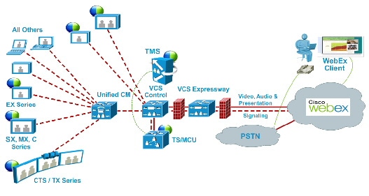
SIP Video, Presentation and Audio
WebEx is deployed using WebEx Audio. Main video, content, and audio to and from the WebEx cloud is negotiated between the Cisco VCS Expressway on the customer site and the WebEx Cloud. All media (main video, content, and audio) flows over IP negotiated using SIP. Blue and green balls symbolize WebEx-enabled endpoints (ball displayed on endpoint display) (OBTP).
Figure 1-4 Network Topology – SIP Video, Audio and Presentation
SIP Video, Presentation and PSTN Audio
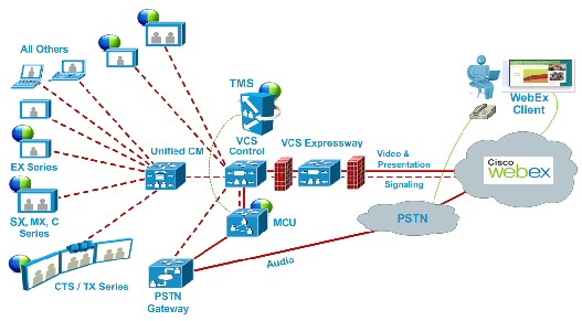
WebEx is deployed using WebEx Audio using PSTN. Only main video and content is negotiated through the VCS Expressway on the customer site and WebEx cloud (SIP/IP).
At the time of scheduling, Cisco TMS provides the MCU PSTN access information (Dial number, Conference ID, Attendee ID). The Cisco MCU calls out and sets up the audio-only call over PSTN to the WebEx cloud, passing the conference ID and attendee ID using DTMF.
This deployment can be set up either of the following ways:
- Using a PSTN gateway registered to Unified CM – See Figure 1-5.
- Using a PSTN gateway registered to VCS – See Figure 1-6.

Note![]() This deployment type is not supported with Cisco TelePresence Server.
This deployment type is not supported with Cisco TelePresence Server.
Figure 1-5 Network Topology – SIP Video and Presentation with PSTN Audio Using Unified CM
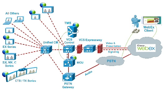
Figure 1-6 Network Topology – SIP Video and Presentation with PSTN Audio Using VCS Control
Cisco TMS Scheduling Role
Cisco TMS provides a control link to the Cisco WebEx site. This interface allows Cisco TMS to book a WebEx enabled meeting on behalf of the WebEx Host, and to obtain Cisco WebEx meeting information that is distributed to meeting participants. Cisco TMS then pushes Cisco WebEx meeting details to the TelePresence Server/MCU.
TelePresence Server and MCU Roles
Cisco TelePresence Server/MCU will send/receive two-way main video with up to 720p30 between WebEx Meeting Center clients and TelePresence endpoints. The MCU/TelePresence Server sends a single transcoded video stream to the WebEx Meeting Center client.
The MCU/TelePresence Server will send a single mixed audio stream of the TelePresence meeting participants to the WebEx cloud. Likewise, the MCU/TelePresence Server will receive a single mixed audio stream from all WebEx participants, including WebEx Meeting Center participants joined over PSTN or VoIP.
Support for two-way content share XGA (1024×768) resolution between telepresence endpoints and WebEx clients.
Each meeting creates its own SIP connection to avoid Transmission Control Protocol (TCP) congestion and potential TCP windowing issues.
Presentation Display Details for Multiple Presenters
For TelePresence users to present, the presenter connects the video display cable to the endpoint and (if necessary) presses a presentation button on the endpoint. When multiple TelePresence users are presenting at the same time, the endpoint that started presenting last is the one that is displayed. As cables are unplugged, the next presenter must start presenting again.
For WebEx users to present, they grab the ball and then select the content to present. If a WebEx user cannot grab the ball, the host must pass it to them. Alternatively, they can use the host key to become the new host.

Note![]() The WebEx site can be provisioned so that any WebEx attendee can grab the ball to present without the host passing them the ball or using the host key.
The WebEx site can be provisioned so that any WebEx attendee can grab the ball to present without the host passing them the ball or using the host key.
Meeting Participant List
The TelePresence participant list, a roster of endpoint names currently connected to the TelePresence Server (if used), is displayed on the TelePresence endpoint display device. MCU and certain endpoint models do not support this feature.
The TelePresence participant list is not, however, displayed in the participant list available to WebEx users. WebEx users see only other WebEx participants and one participant called “TelePresence systems” that identifies all TelePresence participants in the meeting.
Understanding Cisco WebEx Enabled TelePresence Scheduling Flow
This section describes what takes place when a Cisco WebEx Enabled TelePresence Meeting is scheduled using the following:
- Scheduling with the Cisco WebEx and TelePresence Integration to Outlook
- Scheduling with the Cisco Smart Scheduler
- Scheduling with the Cisco WebEx Scheduling Mailbox

Note![]() Multiple deployments are possible at the same time. For example, when using Smart Scheduler, if Microsoft Exchange is deployed, the calendar of any rooms booked for a meeting is updated with the meeting details.
Multiple deployments are possible at the same time. For example, when using Smart Scheduler, if Microsoft Exchange is deployed, the calendar of any rooms booked for a meeting is updated with the meeting details.
Scheduling with the Cisco WebEx and TelePresence Integration to Outlook
Figure 1-7 Cisco WebEx and TelePresence Integration to Outlook Scheduling Flow
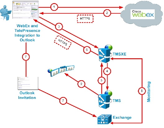
Table 1-2 Cisco WebEx and TelePresence Integration to Outlook Scheduling Steps
Scheduling with the Cisco Smart Scheduler
Figure 1-8 Cisco WebEx Smart Scheduler Scheduling Flow
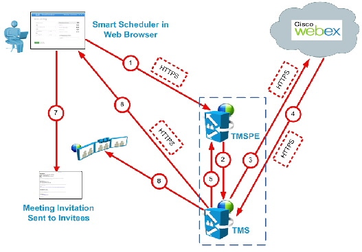
Table 1-3 Cisco Smart Scheduler Scheduling Steps
Scheduling with the Cisco WebEx Scheduling Mailbox
Figure 1-9 Cisco WebEx Scheduling Mailbox Scheduling Flow
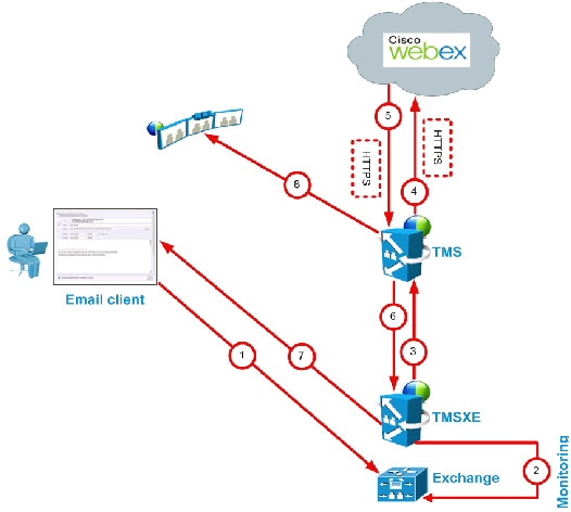
Table 1-4 Cisco WebEx Scheduling Mailbox Scheduling Steps
Understanding Cisco WebEx Enabled TelePresence Call Flow
This section describes the call flow of the following Cisco WebEx Enabled TelePresence Meetings:
- SIP Audio Call Flow
- TSP Audio Call Flow with API Command to Unlock Waiting Room
- TSP Audio Call Flow with Waiting Room and MCU/TelePresence Server as Host
- WebEx Audio (PSTN) Call Flow
SIP Audio Call Flow
Figure 1-10 SIP Audio Call Flow
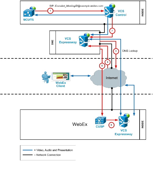
Table 1-5 SIP Audio Call Flow Steps
TSP Audio Call Flow with API Command to Unlock Waiting Room
Figure 1-11 TSP Audio Call Flow with API Command to Unlock Waiting Room
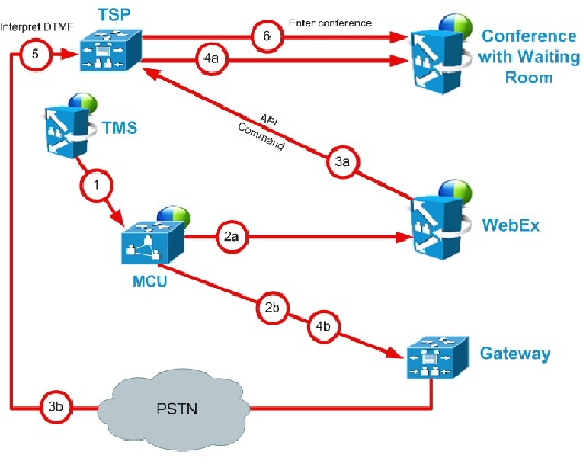
Table 1-6 TSP Audio Call Flow with API Command to Unlock Waiting Room Steps
|
TMS starts the conference on MCU/TelePresence Server, providing it with the SIP URI, telephone number (if using PSTN audio) and DTMF String (if using PSTN audio) to dial into WebEx |
|
|
MCU/TelePresence Server dials WebEx via SIP. (refer to Figure 1-10 for details). |
|
|
At the same time as step 2a, MCU/TelePresence Server dials PSTN call-in number for WebEx. |
|
|
WebEx notifies TSP provider using API command to start the audio conference, and as part of that, Webex tells the TSP provider that the conference type = telepresence and that it should unlock the waiting room. |
|
|
At the same time as step 3a, TSP provider prompts the MCU/TelePresence Server for the meeting access number. |
|
|
At the same time as step 4a, MCU/TelePresence Server sends DTMF tones it was prompted for in step 3b to TSP. |
|
|
TSP provider places MCU/TelePresence Server into the audio conference. |
TSP Audio Call Flow with Waiting Room and MCU/TelePresence Server as Host
Figure 1-12 TSP Audio Call Flow with Waiting Room and MCU/TelePresence Server as Host
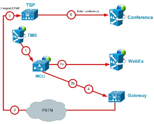
Table 1-7 TSP Audio Call Flow with Waiting Room and MCU/TelePresence Server as Host Steps
|
TMS starts conference on MCU/TelePresence Server, providing it with the SIP URI, telephone# (if using PSTN audio) and DTMF String (if using PSTN audio) to dial into WebEx |
|
|
MCU/TelePresence Server dials webex via SIP. (refer to Figure 1-10 for details). |
|
|
At the same time as step 2a, MCU/TelePresence Server dials PSTN call-in number for WebEx. |
|
|
TSP provider prompts the MCU/TelePresence Server for the meeting access number and host key. |
|
|
MCU/TelePresence Server sends DTMF tones and host key it was prompted for in step 3. |
|
|
TSP provider unlocks the waiting room and places the MCU/TelePresence Server into the audio conference. |
WebEx Audio (PSTN) Call Flow
Figure 1-13 WebEx Audio (PSTN) Call Flow
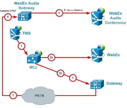
Table 1-8 WebEx Audio Call Flow Steps
|
TMS starts conference on MCU, providing it with the SIP URI, telephone number and DTMF string to dial into WebEx. |
|
|
MCU dials WebEx via SIP. (refer back to Figure 1-10 for details). |
|
|
At the same time as step 2a, MCU dials PSTN call-in number for WebEx. |
|

