- Learn with Cisco at Cisco Live 2025 in San Diego
- This Eufy robot vacuum has a built-in handheld vac - and just hit its lowest price
- I highly recommend this Lenovo laptop, and it's nearly 50% off
- Disney+ and Hulu now offer prizes, freebies, and other perks to keep you subscribed
- This new YouTube Shorts feature lets you circle to search videos more easily
Unique RD per PE in MPLS VPN for Load Sharing and Faster Convergence
Hi Guys ,
I found the below link useful for Designing MPLS load sharing and Fast Convergence.
Original Link# http://lostintransit.se/2015/01/11/unique-rd-per-pe-in-mpls-vpn-for-load-sharing-and-faster-convergence/
This post describes how load sharing and faster convergence in MPLS VPNs is possible by using an unique RD per VRF per PE. It assumes you are already familiar with MPLS but here is a quick recap.
The Route Distinguisher (RD) is used in MPLS VPNs to create unique routes. With IPv4, an IP address is 32 bits long but several customers may and probably will use the same networks. If CustomerA uses 10.0.0.0/24 and CustomerX also uses 10.0.0.0/24, we must in some way make this route unique to transport it over MPBGP. The RD does exactly this by prepending a 64 bit value and together with the IPv4 address, creating a 96-bit VPNv4 prefix. This is all the RD does, it has nothing to do with the VPN in itself. It is common to create RD consisting of AS_number:VPN_identifier so that a VPN has the same RD on all PEs where it exists.
The Route Target (RT) is what defines the VPN, which routes are imported to the VPN and the topology of the VPN. These are extended communities that are tagged on to the BGP Update and transported over MPBGP.
MPLS uses labels, the transport label which is used to transport the packet through the network is generated by LDP. The VPN label which is used to make sure the packets make it to the right VPN is generated by MPBGP and can be per prefix or per VRF.
Below is a configuration snipper for creating a VRF with the newer syntax that is used.
PE1#sh run vrf
Building configuration...

Current configuration : 401 bytes
vrf definition CUST1
 rd 11.11.11.11:1
 !
 address-family ipv4
  route-target export 64512:1
  route-target import 64512:1
 exit-address-family
!
!
interface GigabitEthernet1
 vrf forwarding CUST1
 ip address 111.0.0.0 255.255.255.254
 negotiation auto
!
router bgp 64512
 !
 address-family ipv4 vrf CUST1
  neighbor 111.0.0.1 remote-as 65000
  neighbor 111.0.0.1 activate
 exit-address-family
!
end
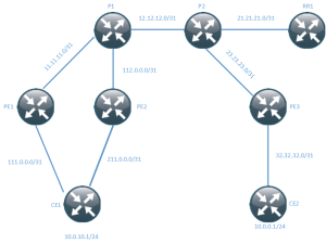
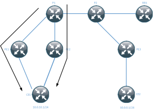
The values for the RD and RT are defined under the VRF. Now the topology we will be using is the one below.
This topology uses a Route Reflector (RR) like most decently sized net works will to overcome the scalability limitations of a BGP full mesh. The negative part of using a RR is that we will have less routes because only the best routes will be reflected. This means that load sharing may not take place and that convergence takes longer time when a link between a PE and a CE goes down.
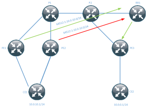
This diagram shows PE1 and PE2 advertising the same network 10.0.10.0/24 to the RR. The RR then picks one as best and reflects that to PE3 (and others). This means that the path through PE2 will never be used until something happens with PE1. This is assuming that they are both using the same RD.
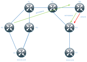
When PE1 loses its prefix it sends a BGP WITHDRAW to the RR, the RR then sends a WITHDRAW to PE3 and then it sends an UPDATE which is the prefix via PE2. The path via PE2 is not used until this happens. This means that load sharing is not taking place and that all traffic destined for 10.0.10.0/24 has to converge.
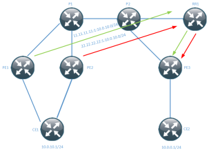
If every PE is using unique RD for the VRF per PE then they become two different routes and both can be reflected by the RR. The RD is then usually written in the form PE_loopback:VPN_identifier. This also helps with troubleshooting to see where the prefix originated from.
PE3 now has two routes to 10.0.10.0/24 in its routing table.
PE3#sh ip route vrf CUST1 10.0.10.0 255.255.255.0

Routing Table: CUST1
Routing entry for 10.0.10.0/24
  Known via "bgp 64512", distance 200, metric 0
  Tag 65000, type internal
  Last update from 11.11.11.11 01:10:52 ago
  Routing Descriptor Blocks:
  * 22.22.22.22 (default), from 111.111.111.111, 01:10:52 ago
      Route metric is 0, traffic share count is 1
      AS Hops 1
      Route tag 65000
      MPLS label: 17
      MPLS Flags: MPLS Required
    11.11.11.11 (default), from 111.111.111.111, 01:10:52 ago
      Route metric is 0, traffic share count is 1
      AS Hops 1
      Route tag 65000
      MPLS label: 28
      MPLS Flags: MPLS Required
The PE is now doing load sharing meaning that some traffic will take the path over PE1 and some over PE2.
We have achieved load sharing and this also means that if something happens with PE1 or PE2, not all traffic will be effected. To see which path is being used from PE3 we can use the show ip cef exact-route command.
PE3#sh ip cef vrf CUST1 exact-route 10.0.0.10 10.0.10.1
10.0.0.10 -> 10.0.10.1 => label 17 label 16TAG adj out of GigabitEthernet1, addr 23.23.23.0
PE3#sh ip cef vrf CUST1 exact-route 10.0.0.5 10.0.10.1
10.0.0.5 -> 10.0.10.1 => label 28 label 17TAG adj out of GigabitEthernet1, addr 23.23.23.0
What is the drawback of using this? It consumes more memory because the prefixes are now unique, in effect doubling the required memory to store BGP Paths. The PEs have to store several copies with different RD for the prefix before it can import it into the RIB.
PE3#sh bgp vpnv4 uni all
BGP table version is 46, local router ID is 33.33.33.33
Status codes: s suppressed, d damped, h history, * valid, > best, i - internal,
              r RIB-failure, S Stale, m multipath, b backup-path, f RT-Filter,
              x best-external, a additional-path, c RIB-compressed,
Origin codes: i - IGP, e - EGP, ? - incomplete
RPKI validation codes: V valid, I invalid, N Not found

     Network          Next Hop            Metric LocPrf Weight Path
Route Distinguisher: 11.11.11.11:1
 *>i 10.0.10.0/24     11.11.11.11              0    100      0 65000 i
Route Distinguisher: 22.22.22.22:1
 *>i 10.0.10.0/24     22.22.22.22              0    100      0 65000 i
Route Distinguisher: 33.33.33.33:1 (default for vrf CUST1)
 *>  10.0.0.0/24      32.32.32.1               0             0 65001 i
 *mi 10.0.10.0/24     22.22.22.22              0    100      0 65000 i
 *>i                  11.11.11.11              0    100      0 65000 i
For the multipathing to take place, PE3 must allow more than one route to be installed via BGP. This is done through the maximum-paths eibgp command.
address-family ipv4 vrf CUST1
  maximum-paths eibgp 2
In newer releases there are other features to overcome the limitation of only reflecting one route, such as BGP Add Path. This post showed the benefits of enabling unique RD for a VRF per PE to enable load sharing and better convergence. It also showed that doing so will use more memory due to having to store multiple copies of essentially the same route. Because multiple routes get installed into the FIB, that should also be a consideration depending on how large the FIB is for your platform.

