- The Apple Watch Ultra 2 is a near-perfect smartwatch and it's $70 off now
- These mainline OnePlus earbuds are a great buy at full price - but now they're $40 off
- These are the Memorial Day sales fitness enthusiasts should pick up
- This tiny 2-in-1 charger solved my biggest problem with traveling - and it's on sale
- Finally, a budget smartwatch that's just as durable as my Garmin (and it's on sale)
VMware Cloud on AWS Terraform deployment – Phase 2

This blog post is a continuation of the phase 1 blog post for Using Terraform with multiple providers to deploy and configure VMware Cloud on AWS. We will pass parameters from one phase to the other. As noted in the phase 1, all source files are available for download here.
Output file from phase 1
In our phase 1, we created an output.tf file with all the parameters we will need in subsequent phase including the NSX-T proxy.
Below is what the output.tf file looks like:
All output parameters in this file come from different modules. For example, we can see how the proxy_url output parameter is sourced from the end of the SDDC module:

Using Terraform functions “trimsuffix” and “trimprefix” we can remove the string https:// and “/sks-nsxt-manager” from the nsxt_reverse_proxy_url output and get the host value needed for the NXST Provider.
After the terraform apply command in Phase 1 the output will be:

State files
After we execute the apply command in Phase 1, Terraform will generate a state file for it named phase1.tfstate. We can read this file and grab output parameters in our deploy.sh script and set our environment with the following three parameters needed for the NSX-T Terraform provider:
- host
- nsxt_username
- nsxt_password

Phase 2 – NSX-T provider
main.tf
Step 1: Set backend for phase 2 state file and read phase 1 state file.

Step 2: Set NSX-T provider

variables.tf
The VMC_subnets variable will hold the details for NSX-T subnets we will create.

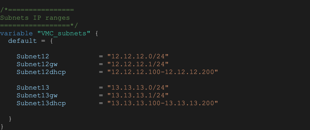
In the main.tf file the NSX module will look like:

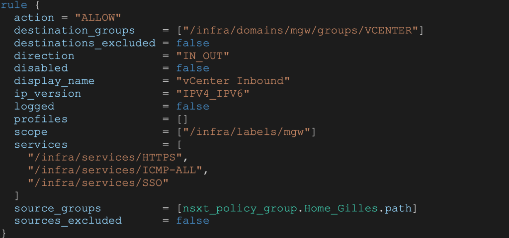
Note that the Home_Gilles variable is for holding my home IP address for a secure vCenter access.
NSX Module
In this module we are going to create the networking and security elements needed in the SDDC. This includes:
- MGW firewall rules
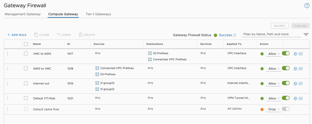
- CGW firewall rules
- NSX segments (12 and 13)
- Compute groups (12 and 13)
- Management group for Home IPs
- Security groups based on NSX tags for Blue VMs and Red VMs
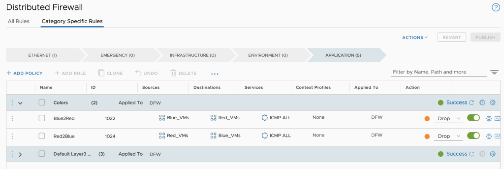
- DFW rules to block ping from Blue VMs to Red VMs
MGW FW rules
Since the VMC Networking environment is pre-build at SDDC creation, we need to use the predefined gateway resource:

For additional protection, we will not allow deletion of this resource using:

The FW rule order in the code is the FW order in the User Interface. As an example, here is the vCenter access rule for my Home IP:
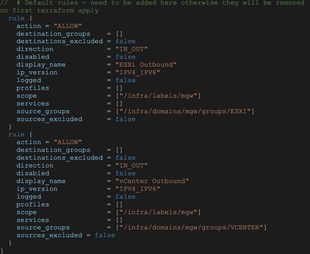
Default rules will need to be added to the code otherwise they will be removed at the first terraform apply execution:
NSX Segments
VMware Cloud on AWS NSX segments are created using the nsxt_policy_fixed_segment resource. DHCP can be coded as well:

Compute and Management groups
The snippet below shows Compute group configuration based on IP address. Note the cgw domain:

Similarly, the snippet below shows Management group configuration. Note the mgw domain:

NSX Security groups and NSX Tags
Next we will create a compute group for Blue VMs:

DFW Firewall rules
In this example we have 2 compute groups created above for Blue VMs and Red VMs. We want to restrict PING between the 2 groups. To do that we can create a security policy named Colors with 2 rules:
- Drop PING from Blue_VNs to Red_VMs groups
- Drop PING from Red_VMs to Blue_VMs groups
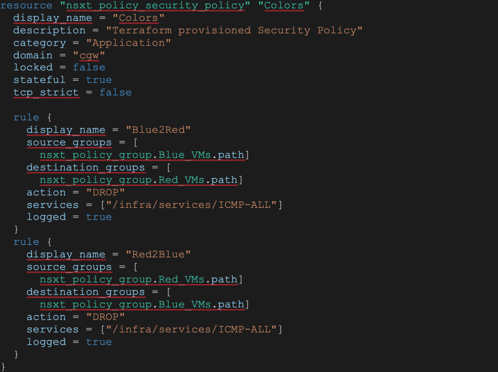
The outputs for this module will be the NSX segment names needed for Phase 3 – vSphere deployment of Virtual Machines.

Phase 2 deployment
After the phase 2 terraform apply in our deploy.sh script, the output will give us:

VMware Cloud Console
Finally, we can review the created network configuration in the VMC Console UI.
Created Segments

Created Groups

Created CGW FW rules
Created DFW rules
In our next and final blog post (phase 3), we will deploy an S3 Content Library and 6 VMs (3 blue and 3 red)
Stay tuned!

