- Offensive Awakening: The 2024 Shift from Defensive to Proactive Security
- Navigating the Digital Age: AI's Crucial Role in Cybersecurity Reinforcement
- Unifying Excellence with Strategic Partnerships: Cisco Black Belt Academy and VQ Communications
- Navigating the API Security Landscape: A CEO's Perspective on Embedding Zero Trust Principles
- Top 5 Global Cyber Security Trends of 2023, According to Google Report

Battle of the Fabrics – The Road to a Future Ready Simple Network

The Evolution of Enterprise Networks for Campus
Digital transformation is creating new opportunities in every industry. In Healthcare doctors can monitor patients remotely and leverage medical analytics to predict health issues. Technology enables a connected campus and more personalized and equal access to learning resources in education. Within retail, shops can provide a seamless, engaging experience in-store and online using location awareness. In the world of finance, technology enables users to securely bank anywhere, anytime, using the device of their choice. In today’s world, digital transformation is essential for businesses to stay relevant.
These digital transformations have required more from networks than ever before. Over time, campus design has been forever changed by the additional demands on the network, each requiring more capabilities and flexibility than previous network designs. Over the past ten years, the enterprise network has continued to evolve from traditional designs to enterprise Fabrics that resemble a service provider design and encompass an Underlay and Overlay.
Fundamentally, it’s essential to understand what typical IT departments, even those segmented within organizations, are attempting to achieve. Ultimately, each company has an IT department to deliver applications that the company relies on to achieve some aim, whether for the public good or for monetary reasons, which could take on many forms, from Manufacturing to Retail, to Financial and beyond. If you look at the core ask, these organizations want a service delivered at some service level to ensure business continuity. For that reason, when the organization introduces new applications or devices, we need to flexibly adopt these new entities securely and simultaneously roll these changes out to the network.
Additionally, more emphasis is being placed on pushing configuration changes quickly, accurately, securely, and at scale while balancing that with accountability. Automation and orchestration are critical to the network of the future, and the ability to tie them into a platform that not only applies configuration but also measures success through both application and user experience is fundamental.
For any organization to successfully transition to a digital world, investment in its network is critical. The network connects all things and is the cornerstone where digital success is realized or lost. The network is the pathway for productivity and collaboration and an enabler of improved end-user experience. And the network is also the first line of defense in securing enterprise assets and intellectual property.
Essentially, everyone in networking is looking for the easy button. We all are looking to reduce the number of devices and complexity while maintaining the flexibility of supporting the business’s priorities from both an application and endpoint perspective. Suppose we can simplify and have the highest available network of the future, which is easily extensible, flexible enough to meet our needs, and is at the same time fully automated and provides telemetry. In that case, we can look at it simply, then perhaps we would head toward that nirvana.
A Fabric can be that solution and is the road to a future-ready, simple network. We remove the reliance on 15 to 20 protocols in favor of 3 to simplify the operational complexities. We fully integrate all wired and wireless access components and utilize the bandwidth available on many links to support future technologies like Wifi 6E and beyond. We should bond policy as part of the ecosystem and use the network to apply and enforce that policy. We can learn intrinsically from the network with telemetry and use Artificial intelligence and Machine Learning to solve issues in a prompted and even automated way. We will discuss all these concepts in more detail in the next couple of sections.
Fabric Overview
A Fabric is simply an Overlay network. Overlays are created through encapsulation, which adds one or more additional headers to the original packet or frame. An overlay network creates a logical topology to virtually connect devices built over an arbitrary physical Underlay topology.
In an idealized, theoretical network, every device would be connected to every other. In this way, any connectivity or topology imagined could be created. While this theoretical network does not exist, there is still a technical desire to connect all these devices in a full mesh. This is where the term Fabric comes from: it is a cloth where everything is connected. An Overlay (or tunnel) provides this logical full-mesh connection in networking. We would then automate the build of these networks of the future using fewer protocols, replacing or eliminating older L2/L3 protocols (often up to 15-20 protocols) and replacing them with as few as 3 protocols. This allows us to have a simple, flexible, fully automated approach where wired and wireless can be incorporated into the Overlay.
Underlay
The Underlay network is defined by the physical switches and routers used to deploy the Fabric. All network elements of the Underlay must establish IP connectivity via the use of a routing protocol. The Fabric Underlay supports any arbitrary network topology. Instead of using arbitrary network topologies and protocols, the underlay implementation for a Fabric typically uses a well-designed Layer 3 foundation inclusive of the Campus Edge switches, known as a Layer 3 Routed Access design. This ensures the network’s performance, scalability, resiliency, and deterministic convergence.
The Underlay switches support the physical connectivity for users and endpoints. However, end-user subnets and endpoints are not part of the Underlay network and have become part of the automated Overlay network.
Overlay
An Overlay network is a logical topology used to virtually connect devices and is built over an arbitrary physical Underlay topology. The Fabric Overlay network is created on top of the Underlay network through virtualization, creating Virtual Networks (VN). The data, traffic, and control plane signaling are contained within each Virtual Network, maintaining isolation among the networks and independence from the Underlay network. Multiple Overlay networks can run across the same Underlay network through virtualization.
Virtual Networks
Fabrics provide Layer 3 and Layer 2 connectivity across the Overlay using Virtual Networks (VN). Layer 3 Overlays emulate an isolated routing table and transport Layer 3 frames over the Layer 3 network. This type of Overlay is called a Layer 3 Virtual Network. A Layer 3 Virtual Network is a virtual routing domain analogous to a Virtual Routing and Forwarding (VRF) table in a traditional network.
Layer 2 Overlays emulate a LAN segment and transport Layer 2 frames over the Layer 3 network. This type of Overlay is called a Layer 2 Virtual Network. Layer 2 Virtual Networks are virtual switching domains analogous to a VLAN in a traditional network.
Each frame from an endpoint within a VN is forwarded in the encapsulated tunnel toward its destination. Similarly, older designs may have used labels to encapsulate traffic in MPLS networks. To determine where the destination is, we need some form of tracking capability to determine where the target is and where to forward the packet. This is accomplished by the Control Plane of the Fabric. In older MPLS networks, and those used by service providers, the control plane was a combination of LDP/TDP for propagating labels and BGP, which utilized the augmentations for separating routing into various VN’s.
Control Plane
To forward traffic within each Overlay, we need a way of mapping where the sources and destinations are located. Typically, the IP address and MAC address are associated with an endpoint and are used to define its identity and location in the network. The IP address is used to identify at layer 3 who and where the device is on the network. At layer 2, the MAC address can also be used within broadcast domains for host-to-host communications when layer 2 is available. This is commonly referred to as addressing the following topology. While an endpoint’s location in the network will change, who this device is and what it can access should not have to change.
Additionally, the ability to reduce fault domains and remove Spanning-Tree Protocol (STP) are big differentiators to driving the need for routed access and removing the reliance on technology which often had slower convergence times. To give a Layer 3 Routed Network the same kind of capabilities, we need to first track those endpoints and then forward traffic between them and off the network to destinations when needed for internet connectivity.
This is the role and function of the Control Plane, whose job it is to track Endpoint Identifiers (EID), more commonly referred to as Endpoints within a Fabric Overlay. This allows the Fabric to forward that traffic in an encapsulated packet separating it from the other VN, thus automatically providing Macro Segmentation while allowing it to meander through the Fabric to the destination. There are differing Fabrics, and each Fabric technology utilizes some form of Control Plane to centralize this mapping system which both the borders and edge nodes rely on. Each technology has its pros and cons, which come to form caveats that we must adhere to when designing and correctly choosing between Fabric technologies.
Locator/ID Separation Protocol (LISP)
Cisco Software-Defined Access (Cisco SD-Access) utilizes the Locator/ID Separation Protocol (LISP) as the Control Plane protocol. LISP simplifies network operations through mapping servers and allows the resolution of endpoints within a Fabric. One of the benefits of this approach is that it is utilized for prefixes not installed in the Routing Information Base. Thus, this is not impactful to edge switches with smaller memory and CPU capabilities to the larger core devices and allows us to expand the Fabric right down to the Edge.
LISP ratified in RFC 6830 allows the separation of identity and location through a mapping relationship of these two namespaces: EID in relationship to its Routing LOCator (RLOC). These EID-to-RLOC mappings are held in the mapping servers, which are highly available throughout the Fabric and which resolve EIDs to RLOCs in the same way Domain Name Servers (DNS) servers resolve web addresses using a PULL type update. This allows for greater scale when deploying the protocols that make up the Fabrics Control Plane. It allows us to fully utilize the capabilities of both Virtual Networks (namespaces) and encapsulation or tunneling. Traffic is encapsulated from end to end, and we will enable the use of consistent IP addressing across the network behind multiple Layer 3 anycast gateways across multiple edge switches. Thus instead of a push from the routing protocol, conversational learning occurs, where forwarding entries are populated in Cisco Express Forwarding only where they are needed.

Instead of a typical traditional routing-based decision, the Fabric devices query the control plane node to determine the routing locator associated with the destination address (EID-to-RLOC mapping) and use that RLOC information as the traffic destination. In case of a failure to resolve the destination routing locator, the traffic is sent to the default Fabric border node. The response received from the control plane node is stored in the LISP map cache, driving the Cisco Express Forwarding (CEF) table and installed in hardware. This gives us an optimized forwarding table without needing a routing protocol update and saves CPU and memory utilization.
Border Gateway Protocol (BGP)
Conversely, Border Gateway Protocol (BGP), which has been heavily augmented over the years, was initially designed for routing between organizations across the internet. Kirk Lougheed and Len Bosack of Cisco and Yakov Rekhter of IBM at an Internet Engineering Task Force (IETF) conference co-authored BGP RFC 1105 in 1989. Cisco has been heavily vested in innovations, maintenance, and adoption of the protocol suite ever since and, over the years, has helped design and added various capabilities to its toolset. BGP forms the core routing protocol of many service provider networks, primarily because of its ability to have a policy-based routing approach. BGP and its routes are installed in the Routing Information Base (RIB) within the network devices of the Fabric. Updates are provided by the protocol to a full mesh of BGP nodes in a PUSH-type fashion. While they can be controlled via policy, by default, all routes are typically shared.
As BGP consumes space within the RIB, let’s evaluate this further, as the implications are extensive. Each device in a Dual-Stack network (IPv4 and IPv6 enabled) utilizes two entries for IPv4 networks, the MAC Address and the IPv4 address as its network prefix. This is effectively 1 network prefix with 2 EID for each endpoint in IPv4. Similarly, in IPv6, each EID would have a Link-Local address, a host address, and a multicast type address entry similar to the network prefix. Each IPv6 address consumes 2 entries per address, and thus we have another 4 entries per endpoint, all of which would be needed within the RIB on all BGP-enabled nodes within the Fabric as it’s a full mesh design. Additionally, the routing protocol must maintain those adjacencies and update each peer as endpoints traverse the Fabric. Due to the processing required in the BGP control plane on every update, there is a higher need for CPU and memory resources as the EID entries change or move within the Fabric.

In the figure above, you will see that utilizing BGP as the control plane requires that the edge device first maintain routing adjacencies, process updates using its algorithm, then install the update in the Forwarding Information Database (FIB) within the CEF table.
Most Access switches or within Fabrics called Edge Nodes have smaller RIB capabilities than the cores they peer with. Typically you will see 32000 entries available on most of the current lines of switching for Edge Nodes. This is quickly consumed by the number of addresses per endpoint, leaving you room for fewer devices if we were not to employ policies and filtering. Thus to accommodate scale, we would need policy, which means we need to modify BGP for its use in a Fabric. As devices roam throughout the network, it is important to understand that updates for each device will be propagated by BGP to every node within that full mesh network. If we were to use our DNS analogy for each roaming event instead of a specific DNS query we force a DNS Zone Transfer.
Another approach is to end the BGP routing at the larger, more powerful core and distribution switches and resort to layer 2 trunks below. Here we would utilize STP, which has slightly slower convergence times in the event of link failures, but all of which can be tuned, but then the network has less reliability and high availability when compared to other solutions. As soon as we need to rely on those Layer 2 protocols, our Fabric has diminished benefits, and we have not achieved the goal of simplification.
Data Plane
In order to forward traffic within each Overlay after sources and destinations are located is the role of the Data Plane. Traffic in Overlays utilizes encapsulation, and many forms of that have been used in various use cases from large enterprises to service provider networks the globe over. In service provider networks, a typical encapsulation is Multi-Protocol Label Switching (MPLS) which encapsulates each packet and utilizes a labeling method to segment traffic. The labeling in MPLS networks was later modified to simplify convergence issues through the use of Segment Identifiers (SID) for Segment Routing. These had several advantages in convergence over the LDP learned labels. Segment Identifiers (SID) were propagated within IGP routing updates of both OSPF and ISIS. This was far superior to the hop-by-hop convergence of LDP, which converged after the IGP came up and was known to cause issues.

We typically utilize Virtual Extensible LAN (VXLAN) in enterprise networks within Fabrics. VXLAN is an encapsulation protocol for tunneling data packets to transport original data packets, unchanged, across the network. This protocol-in-protocol approach has been used for decades to allow lower-layer or same-layer protocols (from the OSI model) to be carried through tunnels creating Overlay like pseudowires used in xConnect.
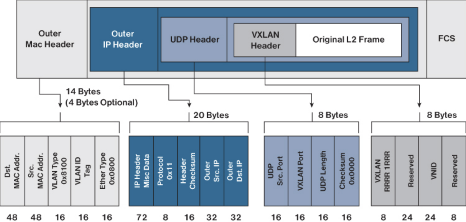
VXLAN is a MAC-in-IP encapsulation method. It provides a way to carry lower-layer data across the higher Layer 3 infrastructure. Unlike routing protocol tunneling methods, VXLAN preserves the original Ethernet header from the original frame sent from the endpoint. This allows for the creation of an Overlay at Layer 2 and at Layer 3, depending on the needs of the original communication. For example, Wireless LAN communication (IEEE 802.11) uses Layer 2 datagram information (MAC Addresses) to make bridging decisions without a direct need for Layer 3 forwarding logic.
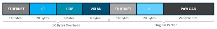
Any encapsulation method is going to create additional MTU (maximum transmission unit) overhead on the original packet. As shown in figure 5 above, VXLAN encapsulation uses a UDP transport. Along with the VXLAN and UDP headers used to encapsulate the original packet, an outer IP and Ethernet header are necessary to forward the packet across the wire. At a minimum, these extra headers add 50 bytes of overhead to the original packet.
Cisco SD-Access and VXLAN
Cisco SD-Access places additional information in the Fabric VXLAN header, including alternative forwarding attributes that can be used to make policy decisions by identifying each Overlay network using a VXLAN network identifier (VNI). Layer 2 Overlays are identified with a VLAN to VNI correlation (L2 VNI), and Layer 3 Overlays are identified with a VRF to VNI correlation (L3 VNI).
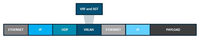
As you may recall, Cisco TrustSec decoupled access that is based strictly on IP addresses and VLANs by using logical groupings in a method known as Group-Based Access Control (GBAC). The goal of Cisco TrustSec technology was to assign an SGT value to the packet at its ingress point into the network. An access policy elsewhere in the network is then enforced based on this tag information. As an SGT is a form of metadata and is a 16-bit value assigned by ISE in an authorization policy when a user, device, or application connects to the network, we can encode (SGT value and VRF values) into the header and carry them across the Overlay. Carrying the SGT within the VXLAN header allows us to utilize it for egress enforcement anywhere in the network and provides Micro and Macro Segmentation capability.
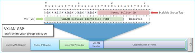
Cisco SD-Access Fabric uses the VXLAN data plane to transport the full original Layer 2 frame and uses LISP as the control plane to resolve endpoint-to-location (EID-to-RLOC) mappings. Cisco SD-Access Fabric replaces sixteen (16) of the reserved bits in the VXLAN header to transport up to 64,000 SGTs using a modified VXLAN-GPO, sometimes called VXLAN-GBP which is backward compatible with RFC 7348.
BGP-EVPN and VXLAN
VXLAN is defined in RFC 7348 as a way to Overlay a Layer 2 network on top of a Layer 3 network. Each Overlay network is called a VXLAN segment and is identified using a 24-bit VXLAN network identifier, which supports up to 16 million VXLAN segments. Without the Cisco modifications to VXLAN, the IETF format would not support SGTs within the header, which would preclude the use of egress enforcement and Micro-Segmentation without forwarding the packet to an enforcement device like a firewall (router on a stick) or deploying downloadable ACL, which add additional load to the TCAM.
Fabric Benefits
When we start to review the various benefits of one Fabric design over the other, there are capabilities that differentiate them. Each Fabric design has something to offer and plays to its strengths. It’s important to clearly understand what benefit you can have from a technology and what the technology solves for you. In this section, we will look at what problems can be solved with each design.
Deploying a Fabric architecture provides the following advantages:
- Scalability — VXLAN provides Layer 2 connectivity, allowing for infrastructure that can scale to 16 million tenant networks. It overcomes the 4094-segment limitation of VLANs. This is necessary to address today’s multi-tenant cloud requirements.
- Flexibility — VXLAN allows workloads to be placed anywhere, along with the traffic separation required, in a multi-tenant environment. The traffic separation is done by network segmentation using VXLAN segment IDs or VXLAN network identifiers (VNIs). Workloads for a tenant can be distributed across different physical devices, but they are identified by their respective Layer 2 VNI or Layer 3 VNI.
- Mobility — IP Mobility within the Fabric and IP address reuse across the Fabric.
- Automation — Various methods may be used to automate and orchestrate the Fabric deployment from a purpose-built controller to Ansible, NSO, and Terraform, thereby alleviating some of the problems with error-prone manual configuration.
Cisco SD-Access
This Fabric technology has many additional benefits that come with its deployment. Cisco SD-Access is built on an Intent-based Networking foundation that encompasses visibility, automation, security, and simplification. Using Cisco DNA Center automation and orchestration, network administrators can implement changes across the entire enterprise environment through an intuitive, GUI-based interface. Using that same controller, they can build enterprise-wide Fabric architectures, classify endpoints for security grouping, create and distribute security policies, and monitor network performance and availability.
SD-Access secures the network at the macro- and micro-segmentation level using Virtual Routing and Forwarding (VRFs) tables and Security Group Tags (SGTs), respectively. This is called Multi-Tier Segmentation, which is not optimal in traditional networks. This segmentation happens at the access port level. This means the security boundary is pushed to the very edge of the network infrastructure for both wired and wireless clients.
With Multi-Tier Segmentation, network administrators no longer have to undertake configurations in anticipation of a user or device move, as all of the security contexts associated with a user or device are dynamically assigned when they authenticate their network connection. Cisco SD-Access provides the same security policy capabilities whether the user or device is attached via a wired or wireless medium, so secure policy consistency is maintained as the user or device changes the attachment type.
Instead of relying on IP-Based security rules as in a traditional network, Cisco SD-Access relies on centralized group-based security rules utilizing SGTs that are IP-address agnostic. As a user or device moves from location to location and changes IP addresses, their security policy will remain the same as their group membership is unchanged regardless of where they access the network. This reduces pressure on network administrators since they do not have to create as many rules or manually update them on different devices. This, in turn, leads to a more dynamic, scaleable, and stable environment for network consumers without reliance on older technologies like PVLANs or constraints of introducing a bottleneck for enforcement.
How can a network be both dynamic and stable at the same time? When a rule does have to be created or changed, it can be done for all users of a group in the Cisco DNA Center. Those rules are then dynamically populated to all relevant network devices that need that rule, ensuring both accuracy and speed for the update. Additionally, wired and wireless network devices may be managed from one automation and orchestration manager, allowing the same rules, policies, and forwarding methods to be adopted across the entire network. With the addition of PxGrid integrations with ISE, the security policies can be adopted by almost any security-enabled platform to dramatically simplify policy enforcement and manageability problems surrounding maintaining ACLs.
When we analyze the solution more deeply and are objective, it is important to understand how the control plane functions and what the ultimate limitations might be of any technology. When a MAC move occurs, and an endpoint (or host) has moved from one port to another. The new port may be within the same edge node, or in a different edge node, in the same VLAN. Each edge node has a LISP control-plane session with all control plane nodes. After an endpoint is detected by the edge node, it is added to a local database called the EID table. Once the host is added to this local database, the edge node also issues a LISP map-register message to inform the control plane node of the endpoint, so the central HTDB is updated. A host may move several times, so each time a move occurs, the HTDB is updated.
Thus there is never a case where the Fabric has the same entry on two edge nodes because this HTDB is utilized as a reference point for Endpoint Tracking when packets are forwarded. Each register message from the edge node includes an EID-RLOC entry for the endpoint, which is a combination of an Endpoint IDentifier (EID) to Resource LOCator (RLOC) mapping. Within LISP, edge nodes would have a management IP or RLOC to identify them individually. As a result, when an edge node receives a packet, it checks its local database for an EID-RLOC entry. If the EID-RLOC entry does not exist, a query is sent to the LISP control plane so the EID may be resolved to the RLOC. This EID-RLOC entry is the mapping of an RLOC to an Endpoint Identifier. Packets and frames received from the endpoint, either directly connected to an edge node or through it by way of an extended node or access point, are encapsulated in Fabric VXLAN and forwarded across the Overlay. Traffic is sent to another edge node or the border node, depending on the destination. When Fabric encapsulated traffic is received for the endpoint, such as from a border node or another edge node, it is de-encapsulated and sent to that endpoint. This encapsulation and de-encapsulation of traffic enable the location of an endpoint to change, as the traffic can be encapsulated towards different edge nodes in the network without the endpoint having to change its address. Additionally, the local database on the receiving edge node is automatically updated during this conversation for the reverse traffic flow. As we mentioned, this conversational learning is precisely that. The updates occur as traffic is forwarded from one switch to another on an as-needed basis. Lastly, most customers want to simplify the management of the network infrastructure but then are looking for the “One ring to rule them all, one ring to find them, One ring to bring them all”, in some sort of Single Pane of Glass. Networking is expansive, with each vendor having its own management platform, and each comes with various capabilities. DNA Center, from a Cisco perspective, allows for the automation and orchestration of Fabrics and Traditional networks from one platform, bringing the power to all of our Enterprise Networking portfolio, but integrating with ISE, Viptela, Meraki, and externally an Ecosystem of products like DNA Spaces, ServiceNow, Infoblox, Splunk Tableau and so many more. Additionally, you can bring your own Orchestrator and orchestrate through DNA Center, which allows organizations to adopt an Infrastructure as Code methodology.
To recap, there are three primary reasons which make it superior to traditional network deployments:
- Complexity reduction and operational consistency through orchestration and automation
- Multi-Tier Segmentation which includes group-based policies, and partitioning at Layer 2 and Layer 3.
- Dynamic policy mobility for wired and wireless clients
- IP subnet pool conservation across the SD-Access Fabric.
BGP-EVPN
BGP EVPN VXLAN can be used as a Fabric technology in a campus network with Cisco Catalyst 9000 Series Switches running Cisco IOS XE software. This solution is a result of proposed IETF standards and Internet drafts submitted by the BGP Enabled ServicesS (bess1) workgroup. It is designed to provide a unified Overlay network solution and also address the challenges and drawbacks of existing technologies proposed BGP to carry Layer 2 MAC and Layer 3 IP information simultaneously. BGP incorporates Network Layer Reachability Information (NLRI) to achieve this. With MAC and IP information available together for forwarding decisions, routing and switching within a network are optimized. This also minimizes the use of the conventional “flood and learn” mechanism used by VXLAN and allows for scalability in the Fabric. EVPN is the extension that allows BGP to transport Layer 2 MAC and Layer 3 IP information. This deployment is called a BGP EVPN VXLAN Fabric (also referred to as VXLAN fabric).
This solution would provide a Fabric comprised of Industry standards-based protocols, which provided a unified Fabric across Campus and Data Centers. Additionally, this Fabric would be interoperable with 3rd party devices in that it would allow for multi-vendor support and, at the same time, be Brownfield-friendly. Additionally, it would allow for rich multicast support with Tennant Routed Multicast and both L2 and L3 support.
This solution also may be deployed and managed by various automation and orchestration methods, from Ansible, Terraform, and Cisco’s NSO platform. While these platforms do offer robust automation and orchestration methods, they do not have the monitoring capability to look at model-driven telemetry. Additionally, they do not tie the richness of Artificial Intelligence and Machine Learning into the solution for help with Day N operations like troubleshooting and faultfinding, and visibility into both the user and application experience requires a separate platform. This often means standing up a separate platform for some sort of visibility, but they are separate and not combined.
When we analyze the solution more deeply and are objective it is important to understand how the control plane functions and what the ultimate limitations might be of any technology. When a MAC move occurs, and an endpoint (or host) moves from one port to another. The new port may be within the same VTEP, or in a different VTEP, in the same VLAN. The BGP EVPN control plane resolves such moves by advertising MAC routes (EVPN route type 2). When an endpoint’s MAC address is learned on a new port, the new VTEP it is in advertises (on the BGP EVPN control plane) that it is the local VTEP for the host. All other VTEPs receive the new MAC route. A host may move several times, causing the corresponding VTEPs to advertise as many MAC-based routes. There may also be a delay between the time a new MAC route is advertised and when the old route is withdrawn from the route tables of other VTEPs, resulting in two locations briefly having the same MAC route. Here, a MAC mobility sequence number helps decide the most current of the MAC routes. When the host MAC address is learned for the first time, the MAC mobility sequence number is set to zero. The value zero indicates that the MAC address has not had a mobility event, and the host is still at the original location. If a MAC mobility event is detected, a new Route type 2 (MAC or IP advertisement) is added to the BGP EVPN control plane by the new VTEP below which the endpoint moved (its new location). Every time the host moves, the VTEP that detects its new location increments the sequence number by 1 and then advertises the MAC route for that host on the BGP EVPN control plane. On receiving the MAC route at the old location (VTEP), the old VTEP withdraws the old route. A case may arise in which the same MAC address is simultaneously learned on two different ports. The EVPN control plane detects this condition and alerts the user that there is a duplicate MAC. The duplicate MAC condition may be cleared either by manual intervention, or automatically when the MAC address ages out on one of the ports. BGP EVPN supports IP mobility in a similar manner to the way it supports MAC mobility. The principal difference is that an IP move is detected when the IP address is learned on a different MAC address, regardless of whether it was learned on the same port or a different port. A duplicate IP address is detected when the same IP address is simultaneously learned on two different MAC addresses, and the user is alerted when this occurs. The number of entries is a bit of a concern primarily because as we start to deal with mobility, and as endpoints move around the network, these prefixes being learned and withdrawn puts a strain on the network from a churn perspective. As this occurs, the upper protocols must converge, and as that happens, CPUs can hit their limits. It’s important to understand the scope of the number of endpoints within the network and accommodate this in the design accordingly, especially when dealing with dual-stack networks utilizing IPv4 and IPv6. Additionally, the design must consider, especially for the routed access approach, the number of entries on the access switches and the performance impact thousands of wireless devices moving across the network might have. The last implication of withdrawing routes by sequence number is that it takes time for convergence; this should not be underestimated. Segmentation is provided by Private VLANs. A private VLAN (PVLAN) divides a regular VLAN into logical partitions, allowing limited broadcast boundaries among selected port groups on a single Layer 2 Ethernet switch. The single Ethernet switch’s PVLAN capabilities can be extended over the BGP EVPN VXLAN, enabling the network to build a partitioned bridge domain between port groups across multiple Ethernet switches in the BGP EVPN VXLAN VTEP mode. The integration of PVLAN with a BGP EVPN VXLAN network enables the following benefits:
- Micro-segmented Layer 2 network segregation across one or more BGP EVPN VXLAN switches.
- Partitioned and secured user-group Layer 2 network that limits communication with dynamic or static port configuration assignments.
- IP subnet pool conservation across BGP EVPN VXLAN network while extending segregated Layer 2 network across the Fabric.
- Conservation of Layer 2 Overlay tunnels and peer networks with a single virtual network identifier (VNI) mapped to Primary VLAN.
Summary
To reiterate, what does a “Future Ready Simple Network” look like. The network of the future ideally would be fully automated and orchestrated. It would also be fully integrated and spread the processing amongst many network devices. It would also be devoid of complexities reducing the number of protocols from 15 to 20 down, thereby simplifying deployment, removing convergence issues, and creating a stable network.
In this network of the future, the policy would drive access, and that would allow for end-to-end micro and macro segmentation, as well as enforcement. The policy should be enforced by the network itself, and not just at choke points. Peer devices for inspection should utilize policy driven from a central point, and the network should appear as one ecosystem where intelligence is shared from platform to platform. That sharing of intelligence should be analyzed from various lenses, and then the resultant information should be used to enforce the policy. As much as possible, we should not bring back legacy protocols that were challenging in the past, and rely on new futuristic lightweight methods.
The network additionally should integrate all forms of access. As we look to the future of access, the wireless speeds we have seen will only increase. Wireless, cannot be an afterthought or a bolt-on product; it should be completely integrated if we are to remove bottlenecks created by forwarding through a common platform a Campus’s entire wireless traffic. Controllers of the future could be overwhelmed easily, and so too could the environments they sit in. A better plan is to spread the load over the network and make use of the robust uplinks forwarding wireless data traffic in the same way that wired traffic is forwarded. This implies that the wireless network of the future must have the ability to forward traffic within the network and preferably in VXLAN.
Additionally, as we speak to mobility, a common IP address schema within a Virtual Network is a real benefit. it reduces the number of subnets to manage, and Fabrics of the future should accommodate such capabilities. This makes designing the network simpler, and we should no longer be reliant on the IP Address for policy.
While there are many approaches to Fabric design, each one uses varying technology, and as a result, has both caveats and limitations which are tied to the technologies they incorporate. Ultimately, when deciding on the overall design of our infrastructure, we must weigh the pros and cons of each and determine if we can work within the caveats of any technology enough to be able to fully adopt it. It’s also important to strive as much as possible for a fully automated environment and remove the burden of manual configurations and the chance for error. Lastly, it’s also important to be able to listen to the network in a fully integrated way incorporating the richness of AI and ML to help diagnose and quickly remediate issues as they arise.
As you begin to ponder about how you may utilize a Fabric, you should consider all the caveats and capabilities and weigh them. In the final analysis, these are the choices network design engineers have to make, and ultimately, each decision has consequences. I hope this walkthrough has helped in some way to bring to light what a Fabric is and what it attempts to solve. We will leave you with these simple questions to consider:
- Does having multiple islands of the management bring a “Single Pane of Glass”?
- Is my wireless design part of my solution?
- Is my wireless design fully integrated into the same management as the Fabric?
- Am I creating bottlenecks in the network for any reason?
If you found this blog helpful, we’d love to hear what you think.
Ask a question or leave a comment below. Stay connected with Cisco on social!
Share:
